IMPORTANT INFORMATION REGARDING NEW COLORDMD LCD PRODUCTS
Beginning with October 2016 production, all new ColorDMD LCD displays will ship with the company’s new Chroma LED/LCD controller board. This is the same board shipped with all LED products to date. From the player’s perspective, there is no change to form or functionality for new LCD displays. However there are some important updates that impact setup and installation of new displays.
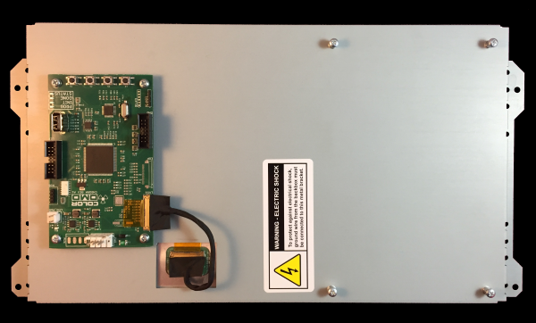
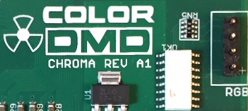
IDENTIFYING CHROMA CONTROLLER BOARDSNew Chroma controller boards, first used in our pilot LED launch, are most easily identified by their vertical mounting orientation on the rear of the display. The ColorDMD logo on Chroma boards includes the version ID “CHROMA REV A1”.Chroma LED and LCD boards may include different connectors to support each configuration. |

|
NEW ROM FILES
Chroma boards employ a more powerful processor chip and requires a different color ROM file than previous boards. These ROM files must be downloaded and saved with the name chroma.rom. (In contrast, ROMs files used with older boards are named colordmd.rom).New ROM files are being generated for the entire library of supported ColorDMD titles and will be listed on the SUPPORT page. The chroma.rom files must be used for new LCD and LED installations. Support for older LCD displays will continue using the original colordmd.rom files.
SINGLE POWER SUPPLY
New LCD and LED displays are designed to operate from a single 12V, 1A, supply. This simplifies installation for customers using external power supplies, and for game platforms like SPIKE where 5V is not readily available.
UPDATED RGB INTERFACEA standard 4-pin +GBR interface connector replaces the 9-pin LAMP_IN connector on previous boards. This interface allows dynamic control of a single display color by an external RGB controller, and easy integration with speaker light kits and other custom control systems.The LAMP_IN connector was also previously used in LCD installations to support illumination of the THING inserts in Addams Family when the original lamp board was removed. Additional holes located at the bottom of LCD brackets now allow the mounting position to be raised in order to provide clearance and use of original lamp boards. |

|